
Date:2025-06-04 Categories:Product knowledge Hits:656 From:Guangdong Youfeng Microelectronics Co., Ltd
3. Circuit Connection
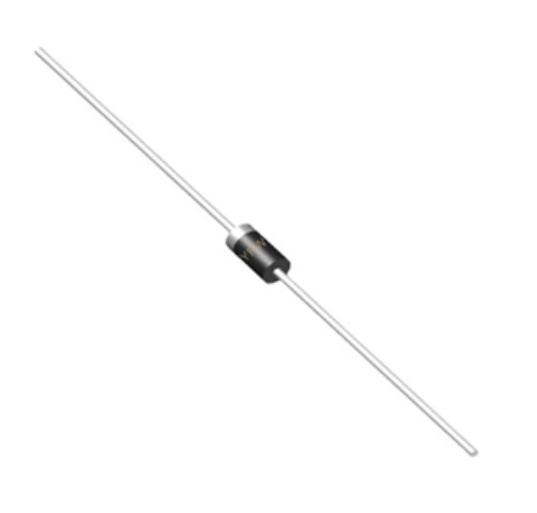
Forward Connection: Connect the anode (positive terminal) of the diode to the higher potential and the cathode (negative terminal) to the lower potential in the circuit. The cathode is usually marked with a stripe or other indicators on the rectifier diode body.
Reverse Connection: In reverse-biased applications, ensure the reverse voltage does not exceed the rated VR. Reverse diodes are often used for protection purposes, such as preventing reverse current flow that could damage other components.rectifier diode
Series and Parallel Connections:
Series Connection: When multiple rectifier diode are connected in series, the total reverse breakdown voltage is the sum of the individual VRs, but the maximum forward current remains limited by the lowest IF of the diodes.
Parallel Connection: Parallel connection can increase the current-handling capability, but each diode should have a series current-limiting resistor to balance the current distribution due to manufacturing tolerances.
4. Installation and Handling
Heat Dissipation: For diodes with higher power dissipation, install them on a heat sink to prevent overheating. Ensure good thermal contact between therectifier diode and the heat sink, and use thermal grease if necessary.
Lead Bending: If bending the leads of the diode, do so at a sufficient distance from the body to avoid mechanical stress that could damage the internal structure. Wait at least 10mm away from the package when bending.
Soldering: Use proper soldering techniques with a soldering iron temperature between 250°C and 300°C. The soldering time should be no more than 3 seconds to prevent thermal damage to therectifier diode. Anti-static measures should be taken to avoid electrostatic discharge (ESD) that may harm the device.
Previous: Classification, Structure, and Principle of MOSFET
Next: Renesas tunable antenna varactor diodes for One-Seg broadcasting applications 1
