Date:2025-02-24 Categories:Product knowledge Hits:754 From:Guangdong Youfeng Microelectronics Co., Ltd
Turn off thyristor (GTO)
Gate Turn Off Thyristor (GTO), also known as Gate Turn Off Thyristor, can be turned off. Its main feature is that the thyristor can automatically turn off when a negative trigger signal is applied to the gate.
As mentioned earlier, ordinary thyristors (SCR) can maintain their on state even after being triggered by a positive gate signal and the signal is removed. To turn it off, the power must be cut off so that the forward current is lower than the holding current IH, or a reverse voltage must be applied to close it off. This requires the addition of a commutation circuit, which not only increases the volume and weight of the equipment, but also reduces efficiency, generates waveform distortion and noise. The switchable thyristor overcomes the above defects by retaining the advantages of high voltage resistance and high current of ordinary thyristors, and has self turn off capability. It is easy to use and is an ideal high-voltage and high current switching device. The capacity and service life of GTO exceed those of giant transistor (GTR), but its operating frequency is lower than that of GTR. At present, GTO has reached a capacity of 3000A and 4500V. High power switchable thyristors have been widely used in fields such as chopper speed regulation, variable frequency speed regulation, and inverter power supply, demonstrating strong vitality.
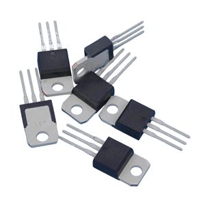
The switchable thyristor also belongs to the PNPN four layer three terminal device, and its structure and equivalent circuit are the same as ordinary thyristors. Therefore, Figure 1 only depicts the appearance and symbols of typical GTO products. Most high-power GTOs are made in modular form.
Although the triggering and conduction principles of GTO and SCR are the same, their turn off principles and methods are completely different. This is because ordinary thyristors are in a deep saturation state after conduction, while GTO can only reach critical saturation after conduction, so adding a negative trigger signal to the gate of GTO can turn it off. One important parameter of GTO is the turn off gain, βoff, It is equal to the ratio of the maximum anode turn off current IATM to the maximum gate negative current IGM, with the formula
βoff =IATM/IGM
The beta off is generally several to tens of times higher. The larger the β off value, the stronger the control ability of the gate current on the anode current. Obviously, β off has similarities with Changsheng's hFE parameters.
The following introduces the methods of using a multimeter to determine the GTO electrode, checking the triggering and turning off capabilities of the GTO, and estimating the turn off gain β off.
1. Determine the electrode of GTO
Set the multimeter to the R × 1 position and measure the resistance between any two pins. Only when the black probe is connected to the G pole and the red probe is connected to the K pole, the resistance will be low. For other situations, the resistance value will be infinite. From this, the G and K poles can be quickly determined, and the remaining pole is A.
2. Check the triggering ability
Firstly, connect the black probe of Table I to pole A and the red probe to pole K, with an infinite resistance; Then use the black pen tip to simultaneously touch the G pole, and with a positive trigger signal, the pointer will deflect to the right to a low resistance value, indicating that the GTO has conducted; Finally, disconnect the G pole. As long as the GTO remains in the on state, it indicates that the tested diode has triggering capability.
3. Check the shutdown capability
The dual meter method is now used to check the shutdown capability of GTO, as shown in Figure 2 (b), while the gear and connection of Table I remain unchanged. Set Table II to R × 10, connect the red probe to the G pole and the black probe to the K pole, and apply a negative trigger signal. If the pointer of Table I swings to infinity to the left, it proves that GTO has the ability to turn off.
4. Estimate the turn off gain β off
When proceeding to step 3, do not connect to Table II first, and record the number of forward deflection cells n1 in Table I when GTO is conducting; Next, force GTO to turn off according to Table II, and record the number of forward deflection grids n2 in Table II. Finally, estimate the turn off gain based on the reading current method using the following formula:
βoff=IATM/IGM≈IAT/IG=K1n1/ K2n2
In the formula, K1 represents the current proportional coefficient of Table I in the R × 1 range;
K2- The current proportional coefficient of Table II in the R × 10 range.
βoff≈10×n1/ n2
The advantage of this formula is that there is no need to calculate the values of IAT and IG specifically. As long as the forward deflection grid numbers of the corresponding hands are read, the turn off gain value can be quickly estimated.
matters needing attention:
(1) When inspecting high-power GTO devices, it is recommended to connect a 1.5V battery E 'in series outside the R × 1 gear to increase the test voltage and current, ensuring reliable conduction of the GTO.
(2) To accurately measure the turn off gain β off of GTO, specialized testing equipment is necessary. But under amateur conditions, the above methods can be used for estimation. Due to different testing conditions, the measurement results are for reference only or as a basis for relative comparison.
Previous: Classification, Structure, and Principle of MOSFET
Next: Renesas tunable antenna varactor diodes for One-Seg broadcasting applications 1