
Date:2025-09-19 Categories:Product knowledge Hits:401 From:Guangdong Youfeng Microelectronics Co., Ltd
In order to obtain the maximum flat second-order Butterworth frequency response, the feedback poles should be set to:
1.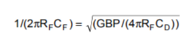
To add the common mode and differential mode input capacitors (0.7+2.8) pF to the 25pF diode source capacitor in Figure 3, and aim for a 50k Ω transient gain using OPA156's 230MHz GBP, the feedback pole needs to be set to 3.8MHz. This will require a total feedback capacitance of 0.8pF. The parasitic capacitance of a typical surface mount resistor is 0.2pF, leaving the required 0.6pF value in Figure 3 to obtain the desired feedback pole.
This will give an approximate -3dB bandwidth setting as:
1.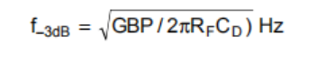
The example in Figure 3 will provide a flat bandwidth of approximately 5.7MHz using 0.6pF feedback compensation.
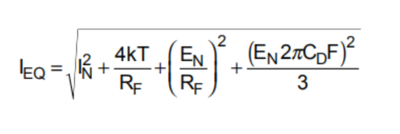
If the frequency band limit of the total output noise is less than the feedback pole frequency (1/RFCF), a very simple expression for the equivalent input noise current can be derived as:
Previous: Classification, Structure, and Principle of MOSFET
Next: Renesas tunable antenna varactor diodes for One-Seg broadcasting applications 1
