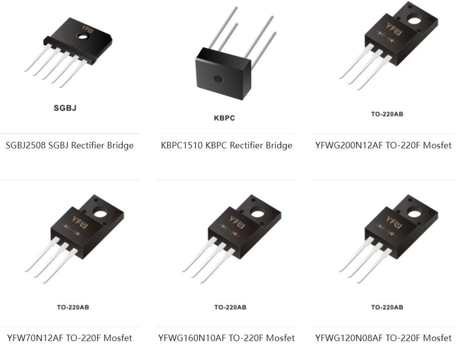
Do you understand the principle and application of rectifier bridge?
The rectifier bridge is to seal the rectifier diodee in a shell. It is divided into full bridge and half bridge.
The full bridge is to seal together the four diodes of the connected bridge rectifier circuit.
Half-bridge is to seal half of two diode bridge rectifiers together, two half-bridges can be used to form a bridge rectifier circuit, and one half-bridge can also form a transformer full-wave rectifier circuit with central tap. The rectifier circuit and working voltage should be considered in choosing the rectifier bridge.
Naming rules.
There are three digits in the general naming of rectifier bridges, the first number represents the rated current, A, and the last two digits represent the rated voltage V (number * 100).
For example, KBL410 is 4A _ 1000V. RS507 is 5A 700V. (1234567 represents 50V, 100V, 100V, 200V, 400V, 400V, 600V, 800V, 1000V respectively).
As a kind of power component, rectifier bridge is very extensive. It is applied to all kinds of power equipment. Its interior is mainly composed of four diodes to convert the input AC voltage into the output DC voltage.
In each working cycle of the rectifier bridge, only two diodes work at the same time, and the alternating current is converted into a unidirectional DC pulsating voltage through the unidirectional conduction function of the diode.
Natural cooling.
Generally speaking, for components with low loss (< 3.0W), natural cooling can be used to solve the heat dissipation problem of components. When the loss of the rectifier bridge is small, natural cooling can be used to deal with it. At this time, the heat dissipation way of the rectifier bridge mainly has the following two aspects: the shell of the rectifier bridge (including the front and rear two large heat dissipation surfaces and the upper and lower heat dissipation surface and the left and right heat dissipation surface) and the four pins of the rectifier bridge.
Forced air cooling.
When the loss of power components such as rectifier bridge is high (> 4.0W), the use of natural cooling can no longer meet the needs of heat dissipation, so forced air cooling must be used to ensure the normal operation of components. When forced air cooling is adopted, it can be divided into two cases: a) the rectifier bridge does not have a radiator; b) the rectifier bridge has its own radiator.
The main results are as follows: 1. In the case of forced air cooling of rectifier bridge without radiator, the analysis process is the same as natural cooling, except that when calculating the thermal resistance of heat dissipation between the shell of rectifier bridge and the heat transfer resistance between PCB plate and environment, the heat transfer coefficient should be selected according to the case of forced air cooling, and its value is usually 20~30W/m2C.
The temperature distribution of the substrate of the rectifier bridge radiator is relatively uniform, about 70 ℃. Even at the temperature directly below the four diodes and the outer edge of the back of the rectifier bridge shell in contact with the radiator, there is only a temperature difference of about 5 ℃. This is mainly because the radiator substrate is an aluminum plate with a certain thickness and good thermal conductivity, which can effectively homogenize the non-uniform temperature on the back of the rectifier bridge.
structure.
The rectifier bridge is usually connected by two or four rectifier silicon chips, two for half bridge and four for full bridge. The outside is encapsulated with insulating material, and the high-power rectifier bridge is encapsulated with zinc metal shell outside the insulating layer to enhance the heat dissipation performance.

Contact: Emma Tan
Phone: +8613650089053
E-mail: emma@yfwdiode.com
Add: No.9 Cuibi street,Nancheng,Zhang mutou town,Dongguan City,Guangdong Province